Current Leads Voltage?! Phasor Diagrams Decoded
Ever feel like electrical circuits are speaking a secret language? Like when someone says "current leads voltage" and you're just nodding along, pretending to understand? Well, the secret's out. It's all about phasor diagrams. These nifty little diagrams are the Rosetta Stone to understanding AC circuit behavior, particularly when current gets ahead of voltage. Seriously, they make it all click.
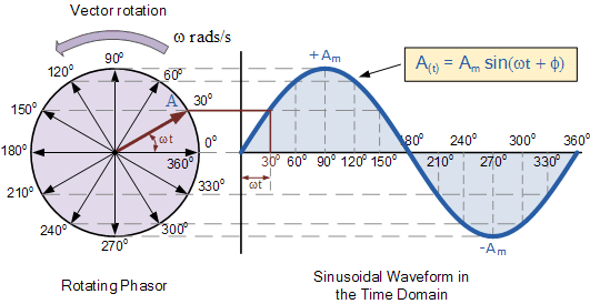
Phasor diagrams visually represent the phase relationship between voltage and current in an alternating current (AC) circuit. Imagine voltage and current as spinning arrows – vectors, if you’re fancy. When current leads voltage, it means the current arrow is ahead of the voltage arrow as they spin. This "lead" is measured as a phase angle, typically denoted by the Greek letter phi (Φ). Why does this matter? It's crucial for understanding power factor and circuit impedance, and that's where things get really interesting.
The concept of leading and lagging current has its roots in the study of reactive components like capacitors and inductors. These components store energy, either in an electric field (capacitors) or a magnetic field (inductors), and this energy storage introduces a phase shift between voltage and current. Capacitors, in particular, cause the current to lead the voltage. Think of it as the current rushing in to charge the capacitor before the voltage fully builds up.
Phasor diagrams are essential tools for electrical engineers, technicians, and anyone working with AC circuits. They're not just theoretical squiggles; they have real-world implications for power system analysis, motor control, and even designing efficient lighting systems. Without understanding these diagrams, you're missing a critical piece of the electrical puzzle.
So, why do we care about this leading current business? In capacitive circuits, the current leads the voltage because the capacitor needs to charge first. This leading current impacts the power factor, a measure of how effectively power is being used in a circuit. A low power factor can lead to wasted energy and increased costs. Phasor diagrams help us visualize and calculate this power factor, enabling engineers to design more efficient systems.
Let's look at a simple example: a circuit with a capacitor. When an AC voltage is applied, the current flows into the capacitor to charge it. This current reaches its peak before the voltage does, resulting in a leading current. The phasor diagram would show the current phasor ahead of the voltage phasor by a certain angle, representing the phase difference.
Benefits of using phasor diagrams include simplifying complex AC circuit analysis, visualizing phase relationships between voltage and current, and facilitating calculations of impedance and power factor. They're like a visual shortcut to understanding circuit behavior.
To construct a voltage-current phasor diagram, you typically choose the voltage as the reference phasor and draw it along the horizontal axis. Then, the current phasor is drawn at an angle relative to the voltage phasor, based on the phase difference. If the current leads the voltage, the current phasor is drawn counterclockwise from the voltage phasor.
Advantages and Disadvantages of Phasor Diagrams
| Advantages | Disadvantages |
|---|---|
| Simplifies complex AC circuit analysis | Can be challenging for complex circuits with multiple components |
| Visualizes phase relationships | Doesn't directly show transient behavior |
| Facilitates impedance and power factor calculations | Requires understanding of vector concepts |
Frequently Asked Questions:
1. What is a phasor? (A rotating vector representing a sinusoidal quantity.)
2. What does it mean when current leads voltage? (Current reaches its peak value before voltage in a cycle.)
3. Why does current lead voltage in a capacitive circuit? (Due to the capacitor's charging behavior.)
4. How is the phase angle calculated? (Using trigonometry and circuit parameters.)
5. What is the significance of the power factor? (Indicates how effectively power is used.)
6. How are phasor diagrams used in motor control? (To analyze motor performance and efficiency.)
7. What software can be used to create phasor diagrams? (MATLAB, LTSpice, etc.)
8. Where can I learn more about phasor diagrams? (Textbooks on circuit analysis, online tutorials.)
Tips and tricks for working with phasor diagrams include using software tools for complex calculations and always double-checking your work to ensure accuracy.
In conclusion, the concept of current leading voltage, visualized through phasor diagrams, is a fundamental aspect of understanding AC circuit behavior. These diagrams provide a powerful tool for simplifying complex analysis, visualizing phase relationships, and calculating critical parameters like impedance and power factor. Mastering the use of phasor diagrams is crucial for anyone working with AC circuits, enabling them to design more efficient and effective electrical systems. From power systems to motor control and even everyday appliances, understanding these diagrams unlocks a deeper understanding of the electrical world around us. So, ditch the confusion and embrace the clarity that phasor diagrams offer. Your future electrical engineering self will thank you.
The power of 20 a pivotal age in tech entrepreneurship
Saying goodnight to your boyfriend the ultimate guide
The unexpected charm of stitch tablet background wallpapers


