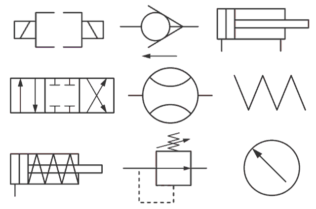
Deciphering Hydraulic and Pneumatic Schematics ISO Symbols
Ever looked at a hydraulic or pneumatic schematic and felt like you were deciphering ancient hieroglyphs? Don't worry, you're not alone. Understanding these diagrams is crucial for anyone working with fluid power systems, and the key to unlocking their secrets lies in mastering the International Organization for Standardization (ISO) symbols.
These standardized symbols represent various components like pumps, valves, actuators, and other elements within a hydraulic or pneumatic circuit. They provide a universal language for engineers, technicians, and operators, enabling clear communication and efficient troubleshooting, regardless of their native language or specific industry.
Imagine trying to explain a complex hydraulic system using only words. It would be a tedious and potentially confusing process. ISO symbols provide a visual shorthand, making it significantly easier to understand the function and interconnection of each component within the system.
The history of these symbols traces back to the need for a standardized way to represent fluid power systems. Before ISO standardization, different manufacturers and regions used their own unique symbols, leading to misinterpretations and difficulties in collaboration. The ISO standards brought clarity and consistency, promoting global understanding and cooperation in the field.
These standardized representations are essential for design, installation, operation, and maintenance of hydraulic and pneumatic equipment. Misinterpreting a symbol can lead to costly errors, system malfunctions, or even safety hazards. Therefore, a firm grasp of these symbols is crucial for anyone involved in fluid power systems.
For example, a simple square represents a reservoir, while a circle with an arrow indicates a directional control valve. These straightforward visual cues make it much easier to understand the system's layout and operation.
Three key benefits of using ISO symbols are enhanced communication, improved safety, and simplified troubleshooting. Standardized symbols allow everyone working with the system to understand its function, reducing the risk of errors. Furthermore, quickly identifying components in a schematic is vital for efficient troubleshooting and maintenance.
To effectively use ISO symbols, familiarize yourself with the standard (ISO 1219-1 for fluid power) and practice reading schematics. Several resources, including textbooks, online tutorials, and dedicated software, can aid in this process.
Creating a checklist of common symbols and their functions can be helpful, particularly for beginners. Regularly reviewing these symbols and practicing their application in real-world scenarios will solidify your understanding and improve your ability to interpret complex diagrams.
Advantages and Disadvantages of ISO Symbols
| Advantages | Disadvantages |
|---|---|
| Universal understanding | Requires initial learning |
| Improved communication | Can be complex for very large systems |
| Enhanced safety | Updates to standards require ongoing learning |
Five best practices for implementing ISO symbols include adhering to the latest ISO standard, using clear and consistent symbols, providing a legend for complex schematics, ensuring proper sizing and spacing of symbols, and regularly reviewing and updating schematics.
Real-world examples include the use of ISO symbols on hydraulic excavators, pneumatic conveyor systems, industrial robots, and even in automotive braking systems. These symbols provide crucial information for understanding and maintaining these complex systems.
A common challenge is keeping up with updates to the ISO standards. The solution is to regularly review the latest revisions and ensure that all schematics are updated accordingly.
Frequently Asked Questions:
1. What is the main ISO standard for fluid power symbols? (ISO 1219-1)
2. Why are ISO symbols important? (For clear communication and safety)
3. Where can I learn more about these symbols? (Textbooks, online resources, etc.)
4. How often are the standards updated? (Periodically, check ISO website)
5. What are some common symbols? (Squares for reservoirs, circles for valves, etc.)
6. How can I improve my understanding of these symbols? (Practice and review)
7. Are there software tools for creating schematics with ISO symbols? (Yes)
8. What is the significance of a triangle in a pneumatic symbol? (Often represents a pilot signal)
A useful tip is to create flashcards with ISO symbols and their corresponding components. This can be a helpful way to memorize and quickly recall the meaning of various symbols.
In conclusion, mastering ISO symbols for hydraulic and pneumatic systems is essential for anyone working in this field. These symbols provide a universal language that facilitates communication, enhances safety, and simplifies troubleshooting. While learning these symbols may require some initial effort, the benefits far outweigh the challenges. By understanding the history, importance, and practical application of these symbols, you can significantly improve your ability to interpret complex schematics, work effectively with fluid power systems, and contribute to a safer and more efficient work environment. Embrace these symbols as your key to unlocking the world of fluid power technology and elevate your understanding to the next level.
Spread holiday cheer with hilarious christmas dad jokes
Bathroom bliss unveiling the tile mystery for your dream tub surround
Li hong yi and cheng yi a deep dive


