Decoding Electrical Schematics: The Secret Language of Switch Symbols
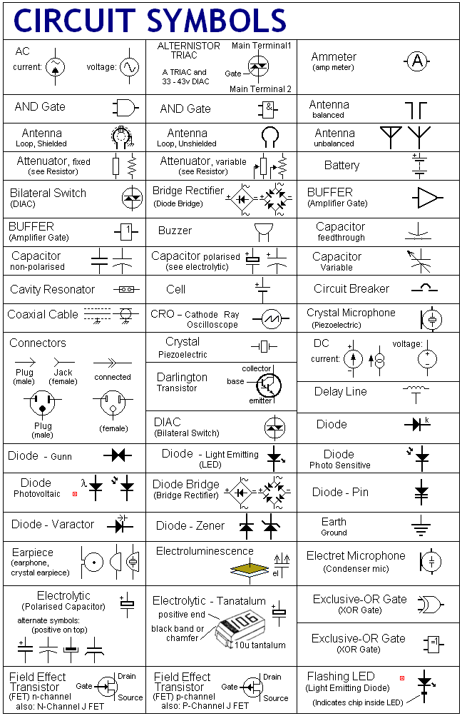
Ever stared at an electrical schematic and felt like you were deciphering hieroglyphics? Those cryptic switch representations aren't random squiggles; they're a crucial part of the electrical blueprint. Understanding electrical switch diagram symbols is like learning the alphabet of circuit design. Without them, you're lost in a world of wires and components.
So, what exactly are these switch symbols in schematic diagrams? They're simplified graphical representations of different types of switches used in electrical circuits. These symbols, standardized over time, allow engineers and technicians to quickly understand the function and connections within a circuit. Think of them as a universal language for electrical design, bridging the gap between concept and reality.
The history of these symbolic representations is intertwined with the development of electrical engineering itself. As circuits became more complex, the need for a standardized visual language became apparent. Early schematic drawings evolved from basic illustrations to the abstract symbols we use today. This evolution reflects the increasing sophistication of electrical systems and the necessity for clear, concise communication.
Why are these schematic switch symbols so important? They're the key to understanding how a circuit operates. Whether you're troubleshooting a faulty appliance or designing a complex electronic system, knowing what each switch symbol represents is essential. Misinterpreting a symbol can lead to anything from a minor malfunction to a catastrophic failure. Accuracy in schematics is paramount.
One of the main issues surrounding switch symbols is the potential for confusion due to variations in standards or outdated diagrams. While standardization efforts have greatly improved consistency, it's still possible to encounter discrepancies. It's crucial to be aware of the specific standards being used in a particular schematic and to double-check interpretations if there's any doubt. This diligence can save time, money, and prevent potentially hazardous situations.
A single-pole single-throw (SPST) switch, represented by a simple line with a break and an angled line connecting to it, controls one circuit. A single-pole double-throw (SPDT) switch, visualized with a line and two angled lines extending from it, controls two circuits. These are just two examples of the many switch types represented by specific symbols.
Benefits of using standardized switch symbols include improved communication, reduced design errors, and easier troubleshooting. Imagine trying to decipher a circuit without these standardized symbols. It would be a chaotic mess of wires and components, nearly impossible to understand. These symbols provide clarity and efficiency in electrical design and maintenance.
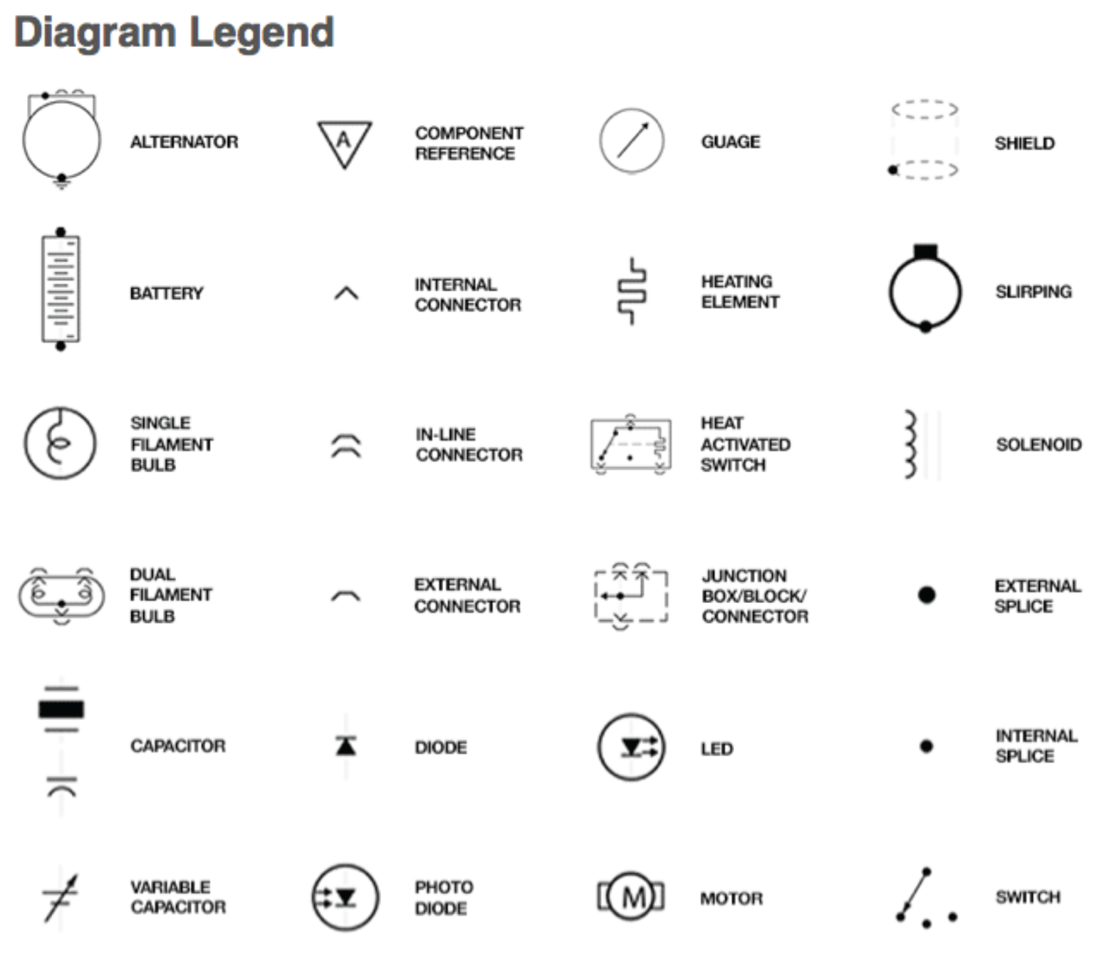
When working with schematics, always cross-reference the symbols with a reliable legend or standard. Don't assume you know what a symbol means. Verify it. This simple practice can prevent costly mistakes. Another crucial step is to ensure the schematic is up-to-date and adheres to current standards.
Advantages and Disadvantages of Standardized Switch Symbols
| Advantages | Disadvantages |
|---|---|
| Clear Communication | Potential for Confusion with Varied Standards |
| Reduced Design Errors | Requires Learning and Understanding of Symbols |
| Simplified Troubleshooting | Can be Complex for Extremely Detailed Circuits |
Best practices include using a clear and concise legend, adhering to relevant standards, and double-checking interpretations. Use software tools designed for creating and analyzing schematics. These tools often have built-in libraries of standard symbols, further reducing the risk of errors.
Real-world examples include the use of switch symbols in automotive wiring diagrams, building electrical plans, and electronic device schematics. These diagrams are essential for understanding the complex electrical systems within these devices and structures.
Challenges include keeping up with evolving standards and dealing with legacy diagrams that may use outdated symbols. Solutions involve using updated resources, consulting with experienced engineers, and utilizing conversion tools to update older schematics.
Frequently Asked Questions:
1. What is a schematic diagram? (A simplified representation of an electrical circuit.)
2. Why are switch symbols important? (They convey the function and type of switch used.)
3. Where can I find a comprehensive list of switch symbols? (Various online resources and engineering handbooks.)
4. How do I interpret a complex schematic diagram? (Start with the basics and break it down into smaller sections.)
5. What are some common mistakes when interpreting switch symbols? (Misidentifying the type of switch due to similar appearances.)
6. Are there different standards for switch symbols? (Yes, variations exist, so ensure consistency.)
7. What software can help with schematic design? (Several CAD and EDA tools are available.)
8. How can I stay updated on the latest switch symbol standards? (Consult relevant industry organizations and publications.)
Tips and tricks: When analyzing complex schematics, break the circuit down into smaller, manageable sections. Focus on understanding the function of each individual component and its connections before tackling the entire system.
In conclusion, understanding schematic diagram switch symbols is fundamental to electrical engineering and related fields. These symbolic representations provide a common language for describing and analyzing circuits, facilitating communication and reducing errors. From the simplest light switch to the most complex integrated circuit, switch symbols are the building blocks of electrical design. Mastery of these symbols empowers engineers, technicians, and hobbyists alike to navigate the intricate world of circuits with confidence. By adhering to best practices and staying updated on the latest standards, you can effectively utilize these symbols to design, analyze, and troubleshoot electrical systems effectively and safely. Take the time to learn these symbols—it's an investment that will pay dividends in your understanding and proficiency in electrical work.
Honoring our heroes a guide to the indiana pa memorial day parade
Unlocking the secrets on your starbucks gift card
Traffic violations and drivers license status what you need to know


