Decoding the Electrical Magnetic Contactor Symbol
Ever glanced at a circuit diagram and felt a twinge of confusion when confronted with a mysterious squiggle or box? Chances are you encountered an electrical symbol, and if it involved switching high-power circuits, it might have been the electrical magnetic contactor symbol. These symbols are the shorthand language of electricians, a visual key to understanding the complex workings of electrical systems. So, what does the electrical magnetic contactor symbol represent, and why is understanding it so crucial?
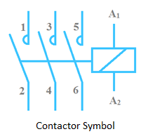
The electrical magnetic contactor symbol depicts a device that controls power to a load, often a motor. Unlike a simple switch flipped by hand, a contactor is operated electromagnetically, allowing remote control and automation. Think of it as a heavy-duty, electrically controlled switch capable of handling much larger currents than a regular switch. This symbol's presence on a diagram indicates the point at which this powerful switching action takes place, providing crucial information for anyone working with the electrical system.
The history of the electrical magnetic contactor symbol is intertwined with the development of industrial automation. Early industrial machinery relied on manual switching, a time-consuming and sometimes dangerous process. The invention of the magnetic contactor revolutionized industrial control, enabling remote operation and automated processes. The symbol itself evolved alongside the technology, standardizing over time to ensure clear communication among electrical professionals. This development boosted efficiency and safety significantly.
The importance of understanding this symbol cannot be overstated. It's the key to interpreting circuit diagrams accurately, a skill vital for electricians, technicians, and engineers. Misinterpreting the symbol could lead to faulty wiring, equipment damage, or even safety hazards. Therefore, a solid grasp of the electrical magnetic contactor symbol empowers professionals to work safely and effectively with these essential components.
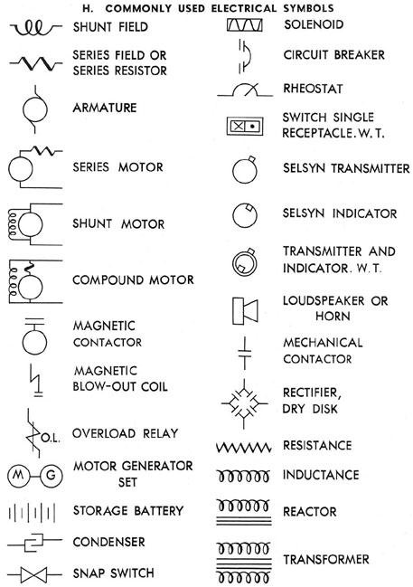
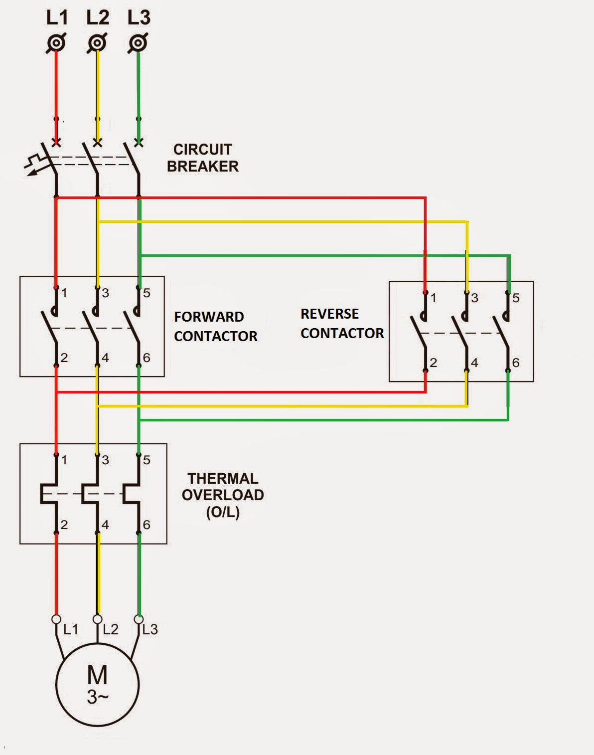
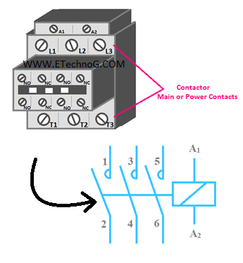
A typical representation of an electrical magnetic contactor in a circuit diagram involves a combination of elements. It often includes a coil symbol, representing the electromagnet that activates the contactor. Connected to the coil are lines signifying the control circuit, which provides the low-voltage signal to energize the coil. The main power contacts, responsible for switching the high-current load, are depicted as parallel lines. Auxiliary contacts, often used for interlocking or signaling, are typically shown as smaller sets of contacts associated with the main contacts.
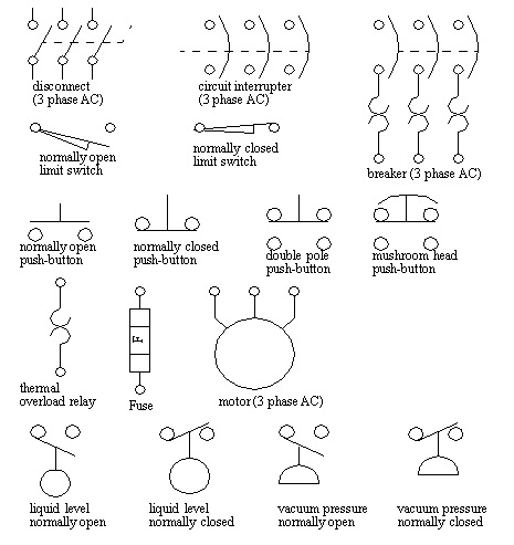
One of the primary benefits of using standardized electrical magnetic contactor symbols is clear communication. These symbols create a universal language understood by electrical professionals worldwide, preventing misunderstandings and ensuring accurate circuit interpretation.
Another advantage lies in simplified circuit design. Symbols condense complex components into easily recognizable icons, making diagrams cleaner and easier to navigate. This streamlined representation speeds up the design process and reduces the risk of errors.
Finally, using these symbols contributes to improved troubleshooting. By recognizing the symbol and understanding its function, technicians can quickly identify and diagnose problems within an electrical system, minimizing downtime and facilitating efficient repairs.
Advantages and Disadvantages
| Advantages | Disadvantages |
|---|---|
| Remote control capability | Requires control circuitry |
| Handles high currents | Can be noisy during operation |
| Automation possibilities | Subject to wear and tear of contacts |
Best Practices:
1. Always consult relevant standards for the correct symbol representation.
2. Ensure consistent use of symbols throughout a diagram.
3. Clearly label all components connected to the contactor.
4. Indicate the coil voltage and contact ratings.
5. Use software tools for creating accurate and professional diagrams.
FAQs
1. What does the coil symbol represent? - The electromagnet that activates the contactor.
2. What are the main power contacts? - The contacts that switch the high-current load.
3. What is the purpose of auxiliary contacts? - Used for interlocking or signaling.
4. Why is standardization of the symbol important? - For clear communication among professionals.
5. How can the symbol aid in troubleshooting? - By facilitating quick identification of faulty components.
6. What are some common problems with contactors? - Contact wear, coil burnout.
7. How can contactor lifespan be extended? - Regular maintenance, proper voltage levels.
8. Where can I find more information about contactor symbols? - Electrical textbooks, online resources.
In conclusion, the electrical magnetic contactor symbol is a fundamental element in the language of electrical diagrams. Its understanding is essential for anyone working with electrical systems. From designing circuits to troubleshooting faults, this symbol plays a critical role in ensuring efficient and safe operation. By mastering its interpretation and applying best practices, professionals can harness the power of magnetic contactors effectively and contribute to the continued advancement of industrial automation. Learning this symbol unlocks a deeper understanding of electrical control systems, empowering professionals to design, operate, and maintain these crucial components efficiently and safely. So, next time you encounter this symbol, remember the power and functionality it represents – a small icon with a significant impact on our electrified world.
What months is cancer sign unlocking the secrets of the crab
Game changers analyzing the greatest first round draft picks
Cincinnatis climate control champions navigating your hvac needs


