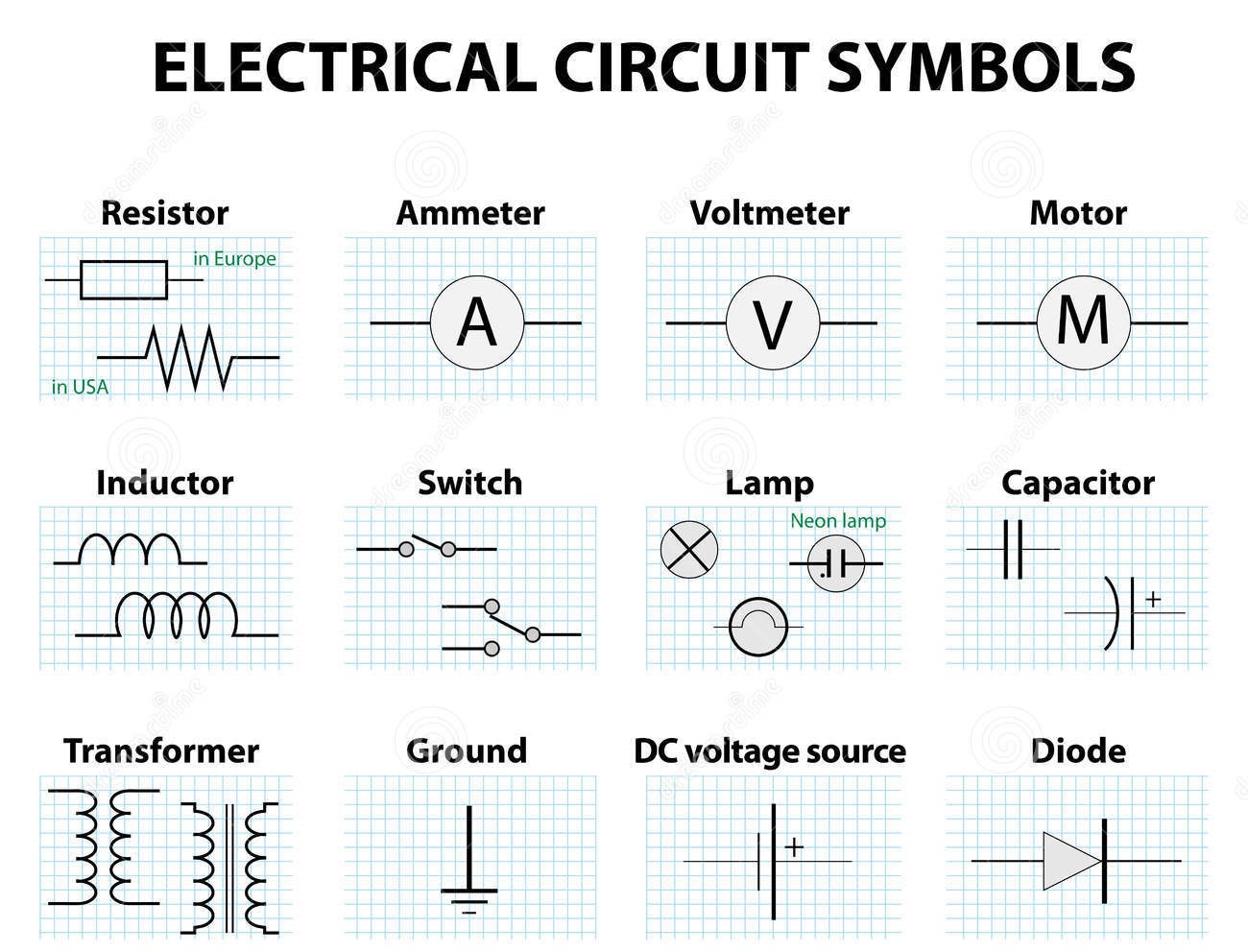
Decoding the Language of Circuits: Electrical Symbols Explained
Imagine trying to assemble a complex piece of furniture with no instructions, just a jumble of parts. Frustrating, right? The world of electrical systems is equally intricate, and without a clear understanding of the language used to represent its components, navigating it would be an impossible task. This is where electrical symbols come in – they're the essential building blocks of communication in electrical engineering, providing a concise and universally understood way to depict circuit elements.
Electrical symbols are graphical representations of electrical and electronic components. Think of them as the words of a language, each conveying a specific meaning about the function of a particular part in a circuit. These standardized symbols allow engineers and technicians worldwide to design, analyze, and troubleshoot electrical systems with efficiency and accuracy.
The journey of these symbols began with the dawn of electrical experimentation. Early pioneers needed a way to record and share their discoveries, so they developed rudimentary symbols to represent batteries, resistors, switches, and other basic components. As electrical systems became more complex, so did the need for a more standardized language. Organizations like the International Electrotechnical Commission (IEC) emerged, playing a crucial role in establishing internationally recognized standards for electrical symbols.
The importance of these standardized symbols cannot be overstated. Imagine the chaos if every engineer used their own unique system of representation! Electrical drawings would become unintelligible across different teams and countries, leading to errors, delays, and potentially dangerous situations. Standardized symbols facilitate collaboration, ensuring that everyone working on a project speaks the same electrical language.
One of the main challenges related to electrical symbols is keeping up with the ever-evolving world of electronics. As new technologies emerge, new symbols must be created and standardized. This requires ongoing collaboration and communication within the electrical engineering community to ensure that everyone is on the same page.
For instance, the symbol for a resistor is a zigzag line, representing the component's resistance to current flow. A battery is represented by two parallel lines of unequal length, indicating the positive and negative terminals. A simple circuit diagram might show a battery connected to a resistor, illustrating a basic closed loop.
Benefits of understanding electrical symbols are numerous. First, they enable clear communication. Second, they simplify complex systems, making them easier to understand and analyze. Third, they are crucial for safety, ensuring that everyone involved in an electrical project can accurately interpret the design and avoid potential hazards.
Creating an action plan for learning electrical symbols can involve starting with the basics, like resistors, capacitors, and switches. Progress gradually to more complex components and circuit diagrams. Utilize online resources, textbooks, and software tools to reinforce your understanding.
Advantages and Disadvantages of Standardized Electrical Symbols
| Advantages | Disadvantages |
|---|---|
| Clear and concise communication | Requires learning and memorization |
| International standardization | Can be complex for intricate systems |
| Facilitates collaboration | Constant updates and additions require ongoing learning |
Best practices include using the latest IEC standards, maintaining consistency in diagrams, and providing clear annotations when necessary. A real-world example would be an electrician using a wiring diagram to install an electrical outlet in a new home. The diagram, full of electrical symbols, guides the electrician on how to connect the wires correctly.
One challenge in using electrical symbols is their sheer number and complexity for advanced circuits. The solution lies in breaking down complex diagrams into smaller, manageable sections and using software tools to assist with interpretation.
FAQs: What is the symbol for a ground connection? What does the symbol for a diode look like? How do you represent a transformer in a circuit diagram? What are the different types of switches and their symbols? How do you read a schematic diagram? What is the difference between AC and DC symbols? Where can I find a comprehensive list of electrical symbols? How do I use these symbols in circuit design software?
Tips include using flashcards to memorize symbols and practicing drawing simple circuits. Remember, mastery of these symbols is essential for anyone working with electrical systems.
In conclusion, electrical symbols are the fundamental language of electrical engineering, enabling clear communication, facilitating collaboration, and ensuring safety in the design, analysis, and maintenance of electrical systems. From basic components like resistors and switches to complex integrated circuits, understanding these symbols is critical. By dedicating time and effort to learning these symbols and their meanings, you’re unlocking the ability to navigate and contribute to the fascinating world of electricity. Embrace the challenge, explore the resources available, and empower yourself with the knowledge to understand and even design the electrical systems that power our modern world. Continuous learning and staying updated with new symbols and standards is crucial for anyone working in this ever-evolving field. So, take the first step today and start decoding the language of circuits!
Discord boy name ideas level up your online persona
Conquering the 6th pick dominate your fantasy football draft
The elusive loch ness monster unraveling the mystery through photos


