Tame Your AC Circuits: Understanding Voltage Phasors
Ever feel like AC circuits are a tangled mess of sines and cosines? Wish there was a simpler way to analyze them without getting lost in the trigonometry? Enter the voltage phasor, your secret weapon for taming these complex circuits. This powerful tool simplifies AC circuit analysis by representing sinusoidal voltages as rotating vectors, making calculations much more manageable.
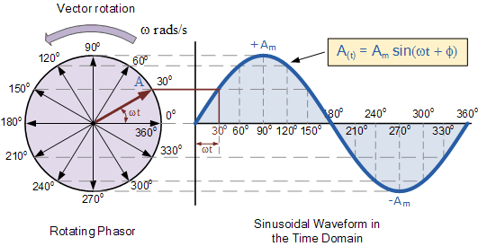
A voltage phasor is a complex number representing the amplitude and phase of a sinusoidal voltage. Think of it as a snapshot of the rotating vector at a specific moment in time. This snapshot captures the essential information about the sinusoidal voltage, allowing us to perform calculations in the frequency domain, a much simpler realm than the time domain.
Imagine trying to add or subtract two sinusoidal voltages with different phases. In the time domain, it involves cumbersome trigonometric identities. With phasors, however, it becomes a simple vector addition or subtraction. This simplification is crucial when analyzing complex circuits with multiple components.
Understanding what a voltage phasor represents opens the door to a more intuitive grasp of AC circuit behavior. Instead of grappling with fluctuating waveforms, we can visualize the interaction of phasors, making circuit analysis more accessible and less intimidating.
The concept of phasors arises from the fundamental relationship between sinusoidal functions and complex exponentials, a cornerstone of mathematics. Charles Proteus Steinmetz, a pioneering electrical engineer, is credited with popularizing the use of phasors in AC circuit analysis. Their importance lies in their ability to transform complex differential equations into simpler algebraic equations, significantly streamlining circuit calculations.
One of the main challenges associated with phasor analysis is understanding the concept of phase shift and its impact on circuit behavior. However, with practice and a clear understanding of the underlying principles, this challenge can be overcome. Let's explore a simple example: a voltage source with an amplitude of 10V and a phase angle of 30 degrees can be represented by the phasor 10∠30°.
Benefits of using voltage phasors are numerous. Firstly, they simplify AC circuit calculations, as mentioned earlier. Secondly, they provide a visual representation of the relationship between voltage and current in a circuit. Lastly, phasors enable the use of powerful circuit analysis techniques like impedance and admittance, further simplifying complex circuit analysis. For example, calculating the total impedance of a series RLC circuit becomes a straightforward addition of complex impedances when using phasors.
To effectively apply phasors, start by converting sinusoidal voltages into their phasor representations. Then, perform circuit analysis using phasor algebra, adding, subtracting, multiplying, and dividing phasors as needed. Finally, convert the resulting phasor back into the time domain to obtain the actual sinusoidal waveform.
Advantages and Disadvantages of Phasor Analysis
| Advantages | Disadvantages |
|---|---|
| Simplifies AC circuit calculations | Requires understanding of complex numbers |
| Provides a visual representation of circuit behavior | Only applicable to sinusoidal waveforms |
| Enables the use of powerful analysis techniques | Can be challenging for beginners to grasp |
Best practices for implementing phasor analysis include: ensuring all sinusoidal voltages are at the same frequency, carefully tracking phase angles, and verifying results by comparing with time-domain analysis for simpler circuits.
Real-world examples of phasor analysis include: analyzing power systems, designing filters, and understanding the behavior of AC motors.
Frequently Asked Questions about Voltage Phasors:
1. What is a voltage phasor? A voltage phasor is a complex number representing a sinusoidal voltage.
2. Why use phasors? They simplify AC circuit analysis.
3. How are phasors related to sinusoidal waveforms? They represent the amplitude and phase of the waveform.
4. How do I convert a sinusoidal voltage to a phasor? Use the amplitude and phase angle.
5. What is the importance of phase angle in phasor analysis? It determines the relative position of the sinusoidal waveform.
6. What are some applications of phasor analysis? Power systems analysis, filter design, AC motor analysis.
7. What is the difference between phasor and vector? Phasors are complex vectors representing sinusoidal quantities.
8. Where can I learn more about phasors? Textbooks on circuit analysis, online resources.
Tips and tricks: Practice converting between sinusoidal waveforms and phasors, visualize phasors as rotating vectors, and start with simple circuits before tackling complex ones.
In conclusion, voltage phasors are a powerful tool for simplifying the analysis of AC circuits. They provide a more manageable approach to dealing with sinusoidal voltages and currents, allowing engineers and students alike to understand and design complex electrical systems. By mastering the concept of voltage phasors, you can unlock a deeper understanding of AC circuit behavior, opening doors to a wider range of applications in electrical engineering. Start utilizing phasors in your circuit analysis today and experience the efficiency and clarity they bring to the world of AC circuits. From simplifying calculations to providing visual insights, voltage phasors are an indispensable tool for anyone working with alternating current systems. Embrace the power of phasors and transform your approach to AC circuit analysis. Don't let complex trigonometric calculations hold you back – unlock the potential of phasors and conquer the world of AC circuits.
Arnold shaking hands gif the internets favorite power move
The weight of 1 exploring the nfls top draft picks
Paris 2024 olympics when are the games


