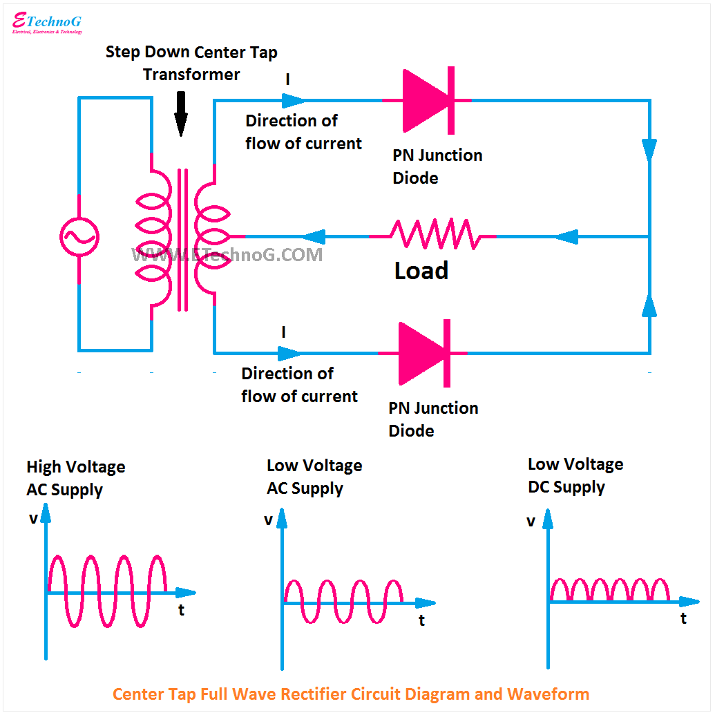
Understanding Half Wave Rectifier Circuits
Ever wondered how alternating current (AC) gets converted to direct current (DC)? One of the foundational building blocks in electronics that accomplishes this is the half wave rectifier. Understanding its schematic, often presented as a half wave rectifier circuit diagram, is crucial for anyone working with electronics.
A half wave rectifier circuit diagram visually represents the components and connections necessary for this AC-to-DC conversion. These diagrams are invaluable resources, providing a clear blueprint for building and troubleshooting these circuits. They allow you to see the flow of current and understand how the diode, a key component, acts as a one-way valve for electricity.
Finding a good representation of a half wave rectifier circuit, ideally in a downloadable format like a PDF, is often the first step in learning about this fundamental electronic concept. These PDFs can be easily saved and referenced, making them ideal for students, hobbyists, and professionals alike. They serve as a quick reference guide during design, construction, and troubleshooting.
The core principle behind half wave rectification is the use of a diode to block one half of the AC cycle. This results in a pulsating DC output. While simple in design, understanding the implications of this pulsating output is critical for selecting the right rectifier for your application. A downloadable half wave rectifier circuit diagram PDF can often provide additional insights into the waveform characteristics.
Grasping the nuances of half wave rectifier circuit diagrams goes beyond just identifying components. It involves understanding the underlying physics, the limitations of the circuit, and its various applications. This knowledge is essential for designing efficient and reliable electronic systems.
The half-wave rectifier, predating more complex rectifier designs, emerged as a simple solution for AC-to-DC conversion. Its early implementations were crucial in the development of radio technology and power supplies. The simplicity of the design, requiring only a single diode, made it a cost-effective choice for many early applications. A key issue with the half-wave rectifier is its inefficient use of the AC input, as it only utilizes one half of the cycle, resulting in a significant ripple in the output DC voltage. This ripple can be problematic for sensitive electronic components.
A half-wave rectifier uses a single diode to allow only one half of the AC waveform to pass through. For example, during the positive half-cycle of the AC input, the diode conducts, allowing current to flow through the load. During the negative half-cycle, the diode blocks the current, effectively clipping that portion of the waveform.
One benefit of a half-wave rectifier is its simplicity. With only a diode and a few other components, it's easy to build and understand. Another benefit is its cost-effectiveness, especially for low-power applications. Finally, its simplicity makes it ideal for educational purposes, allowing beginners to grasp the fundamentals of rectification.
Advantages and Disadvantages of Half Wave Rectifiers
| Advantages | Disadvantages |
|---|---|
| Simple circuit design | Low efficiency (only utilizes half of the AC cycle) |
| Cost-effective | High ripple voltage in the output DC |
| Easy to understand and implement | Not suitable for applications requiring smooth DC output |
Best Practice: Ensure the diode is correctly oriented in the circuit. Reverse bias will block the entire AC signal.
Real Example: Simple battery chargers often use half-wave rectification.
Challenge: High ripple voltage. Solution: Use a filter capacitor to smooth the output DC voltage.
FAQ 1: What is a half-wave rectifier? Answer: A circuit that converts AC to pulsating DC by allowing only one half of the AC cycle to pass.
FAQ 2: What is the main component of a half-wave rectifier? Answer: A diode.
Tip: Use a high-quality diode for better performance and reliability.
In conclusion, the half wave rectifier circuit, often depicted in easily accessible diagram formats like PDFs, represents a fundamental concept in electronics. Understanding its operation, from the basic components like the diode to the resulting pulsating DC output, is crucial. While its simplicity and cost-effectiveness make it suitable for certain applications, its limitations, such as high ripple voltage and low efficiency, must also be considered. By exploring available resources, like detailed diagrams and FAQs, you can gain a comprehensive understanding of this foundational circuit and its role in the world of electronics. This knowledge is essential for anyone seeking to design, build, or troubleshoot electronic systems effectively. Take the time to learn more about half wave rectifiers and unlock the potential of AC-to-DC conversion.
Heart health matters your guide to finding the right cardiologist
Finding peace of mind a guide to ny state prison lookup
Unlocking energy savings your guide to weatherization assistance


